Theory:
In order to optimize custom wheel build quality, I looked for methods to achieve maximum benefit from rear wheel torque by closely studying wheel geometry.
Wheel torque transfer efficiency depends on two spokes angles in relation to the rear hub.
- The first one is the angle the spoke makes when we look at a wheel from the side, as it approaches 90°, the more tangential it is, the better the torque transfer will be. If the spoke is perfectly tangential to the hub, we can state that the longitudinal torque (CL) transfer is 100%. When the spoke is radial, we can state that it’s null, since the spoke will work under a bending load (it’s not made for that) rather than a pulling load.
- The second one is the bracing angle. Look at a rear wheel from the back, it’s the angle between a given spoke and the imaginary line perpendicular from the hub. The closer its to 0°, the more efficient torque transfer will be. If this angle approaches 90°, we can state that the transversal torque (CT) transfer is null. (impossible in practice as it would require an infinite hub width). This angle is always very small, we can consider that it has almost an insignificant effect on torque transfer. (To a far greater extent it’s the angle that effects the lateral stiffness of a wheel).
Total wheel torque will then result in the following equation:

To calculate CL, we take the first angle that is the key feature of longitudinal torque transfer.
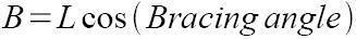
Using a known bracing angle and spoke length, and by projecting it against the imaginary straight line coming from the flange hub axle, we will then find its length on the plane made by the flange.

We can find B through:
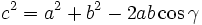
From this length, we’ll apply the Al Kashi theorem in order to calculate the longitudinal torque angle.
Al-Kashi’s theorem reminder; we can apply the generalized Pythagoras formula in a non right-angled triangle.
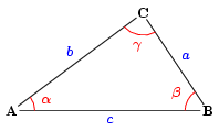
From the B length we just found, we apply this theorem in the following triangle made by the straight lines called A, B and C to calculate the green angle. Actually we’re looking for its complementary angle; the blue one.

We find this formula for TêtaL :
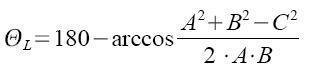
The figure of cos-1 [A2+B2-C2/(2AB)] has to be multiplied by 57.296 when working in radians. It’s derived from 180/pi; the ratio between radians and degrees.
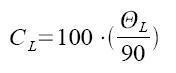
Now we can determine CL; the longitudinal torque transfer efficiency through an easy cross calculus from the perfect transfer (100%) and its angle (90°)
With similar thoughts, we can establish the curve of the transversal torque transfer according to the bracing angle;

L= spoke length
A= flange radius
B= spoke length projected on the plane created by a flange.
C= Effective radius of a rim.
ӨL= Torque transfer angle on the plane created by a flange.
ӨT= Torque transfer angle on the transversal plane created by a flange (bracing angle)
Example:
Example of the rear wheel that was presented a few days ago on Roues Artisanales (Zipp 285, TUNE Mag190, 28 spokes crossed 3 times);
We know L= 273,3mm (theoretically) and ӨT= 4.4° so B= 272,5mm. We then get ӨL = 80° and so CL=88%. In addition, we get CT=95% through the last formula.
We are now able to assess the efficiency of torque transfer on the right hand side of the wheel; CTotal = 84%.
Interpretation:
The efficiency of the right side torque transfer is 84%. It means that when we apply torque to the hub, one spoke in two (the pushing spokes only act while braking) will transmit 84% of the torque by traction.
The last 16% percent will be transmitted through spoke bending. Spokes aren’t made to work under bending loads due to the almost complete lack of rigidity. Meaning, that we have to try and achieve angles for ӨT and ӨL as close to 90° and 0° respectively in order to reduce spoke stress to a minimum.
However, some factory wheels such as the Neutron, that are amongst the strongest and the most reliable we can find on the market, are built with a radial left pattern. It can be explained by the fact that the non drive side transmits less torque than the drive side (balance ratio is around 85%/15%). Meaning, that the left spokes which are submitted to a bending loading is kept to a minimum. Nowadays spoke quality is of such a high level that it doesn’t have a significant impact on durability. Additionally, these wheels use specials nipples that minimize head spoke strain level.
Another "against the grain example " is the Ksyrium wheel, which has a radial spoke pattern on the drive side. This kind of spoke pattern is possible due to extraordinary mechanical properties of the spokes (but they lose tension quickly), a very stiff hub that maximizes torque transmission, and a rim with optimized nipple placement, allowing for the non drive spokes to work almost exclusively under a pulling load.
I wrote this article based on my own knowledge, if you find a problem or you think something is wrong, feel free to contact me.